Heatsink Optimizer
Skills
Summary
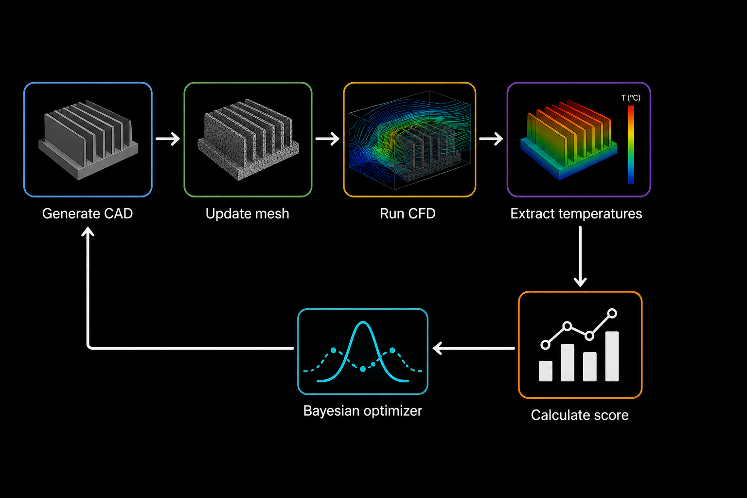
An automated design pipeline that generates heatsink geometry, updates a CFD model, measures thermal performance, and uses Bayesian optimization to choose the next design. The goal is to improve chip cooling without adding unnecessary manufacturing complexity.
View source codeSection 1
Automated Design Loop
Each candidate moves through the same repeatable workflow: generate the CAD model, update the mesh, run the CFD simulation, extract fresh monitor values, and calculate an objective score. The optimizer learns from every completed run before proposing the next geometry.
Section 2
Parametric CAD & CFD
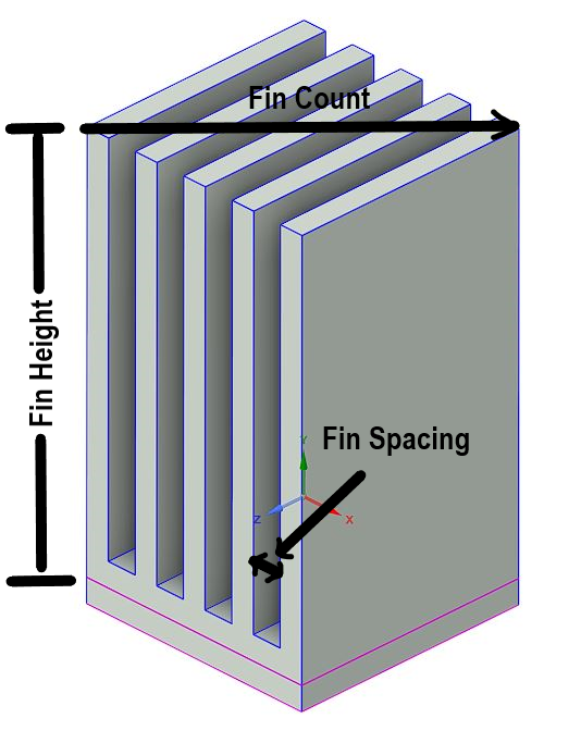
The SpaceClaim script builds the chip, heatsink, fins, and surrounding fluid enclosure from two controlled dimensions: a fin count from one to nine and a fin height between zero and 22 millimetres. The base and fins are merged into one solid, keeping contact regions stable as the topology changes between designs.
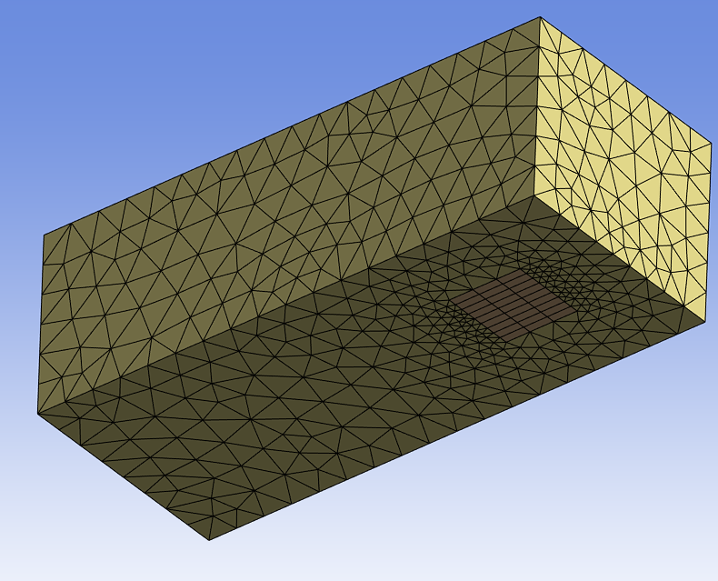
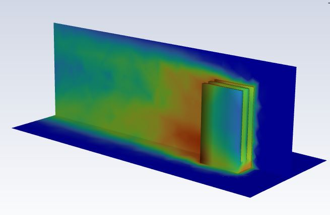
Named selections identify the chip, heatsink, enclosure, inlet, outlet, symmetry plane, and bottom wall. Workbench updates the geometry and mesh before PyFluent loads the saved solver setup, validates the required boundaries, initializes the model, and runs the conjugate heat-transfer calculation.
Section 3
Bayesian Optimization
Reproducible random designs establish the initial data set. A Gaussian process then models the objective across the design space, while expected improvement selects the next combination of fin count and height most likely to outperform the current best design.
Objective score
chip temperature + 0.25 × outlet temperature + 0.5 × additional fins + 0.1 × fin height (mm)
Lower temperatures improve the score, while extra fins and greater fin height add penalties representing manufacturing cost and complexity. The weights and design bounds remain configurable for different cooling priorities.
Section 4
Pipeline & Outputs
A terminal launcher supports either one specified heatsink design or a complete optimization run. Every successful or failed simulation is timestamped in the results log with its settings and monitor values: chip temperature, outlet temperature, and inlet velocity.
The same optimizer can also run against sample data without launching Fluent, making it possible to test the search logic independently from the full Ansys workflow.